Basics of Electronics
Goals of This Chapter
- Obtain a basic understanding of electricity and circuits
An Introductory Spark
MIT Illuminations is just a series of lights coordinated through a computer to turn on at specific colors at specific times. To explain how these lights work, we first have to understand the basics of electricity.
There are two types of electricity: alternating current (AC) and direct current (DC). If you're in the United States (and most countries) the electricity you use whenever you plug in a device to an outlet is AC. When you power a device with a battery, that's a small, safe, and manageable amount of DC.
For this learning guide, we'll be using DC!
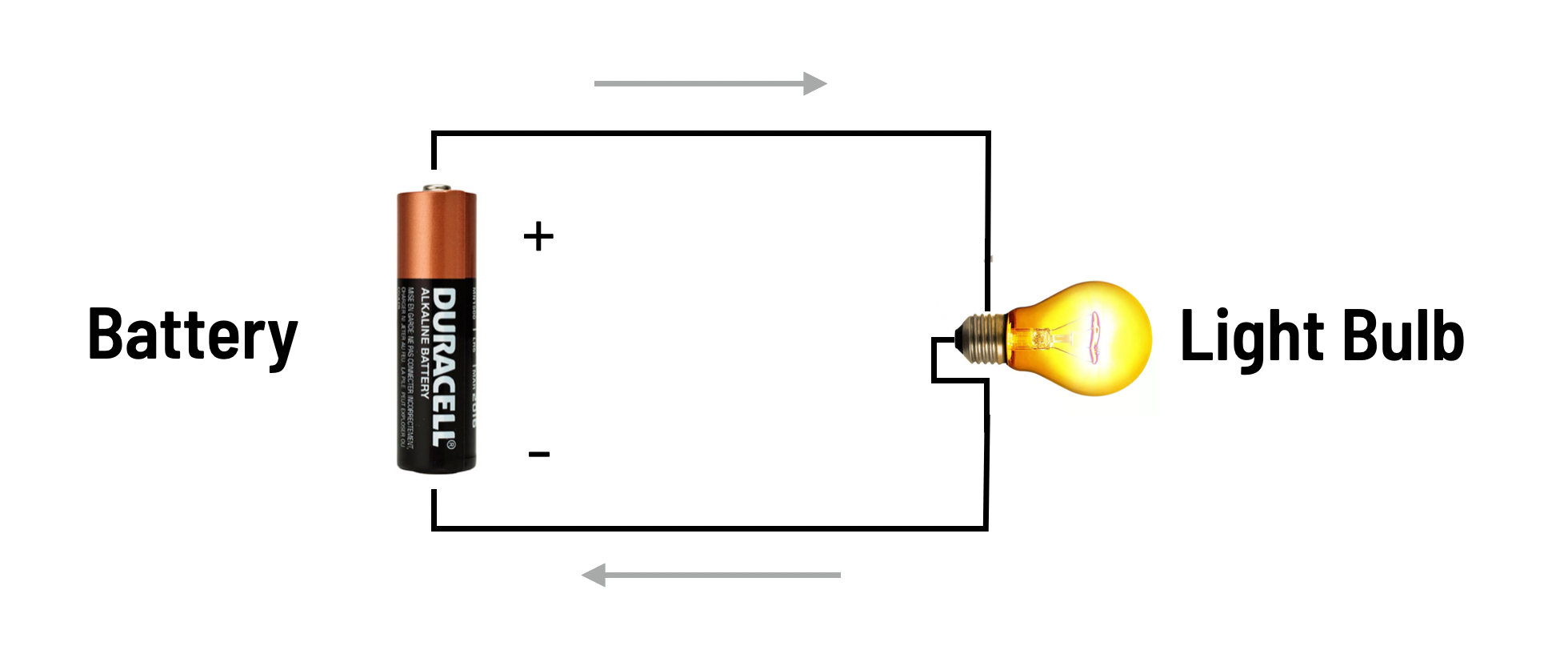
Above you can see a diagram of a simple DC circuit - the electricity is coming from the battery and powering a light bulb. The battery, in this case, is our power source, and the light bulb is our load.
The black lines represent wires. You can see that the top black line - or wire - goes from the positive terminal of the battery to the bulb. And the bottom black line - or wire - goes from the bulb back to the negative terminal of the battery.
Electricity flows in a loop (in the direction of the arrows shown) from the power source to the load and then back. Because this circuit is a complete, unbroken loop, we call it a closed circuit.
If there is a break in the loop, the circuit is incomplete and no electricity will flow. We call that an open circuit. You can think of a circuit as a conveyor belt for electricity - the whole loop has to be connected and intact, otherwise it won't work properly.
Note that the direction of the arrows in our circuit diagram shows theconventional current, which assumes that power flows from the positive battery terminal to the negative battery terminal. The reverse direction is called electron current, which is a more realistic model of the actual flow of electrons. But, for the sake of this project, we don't need to get deep into the physics of electricity.
We have a light!
If you were to build a circuit based on the diagram above, you would see the light turn on! And there are a couple of parameters that you can adjust when you build any circuit. For this project, the things we care about the most arevoltage and amperage.
Voltage
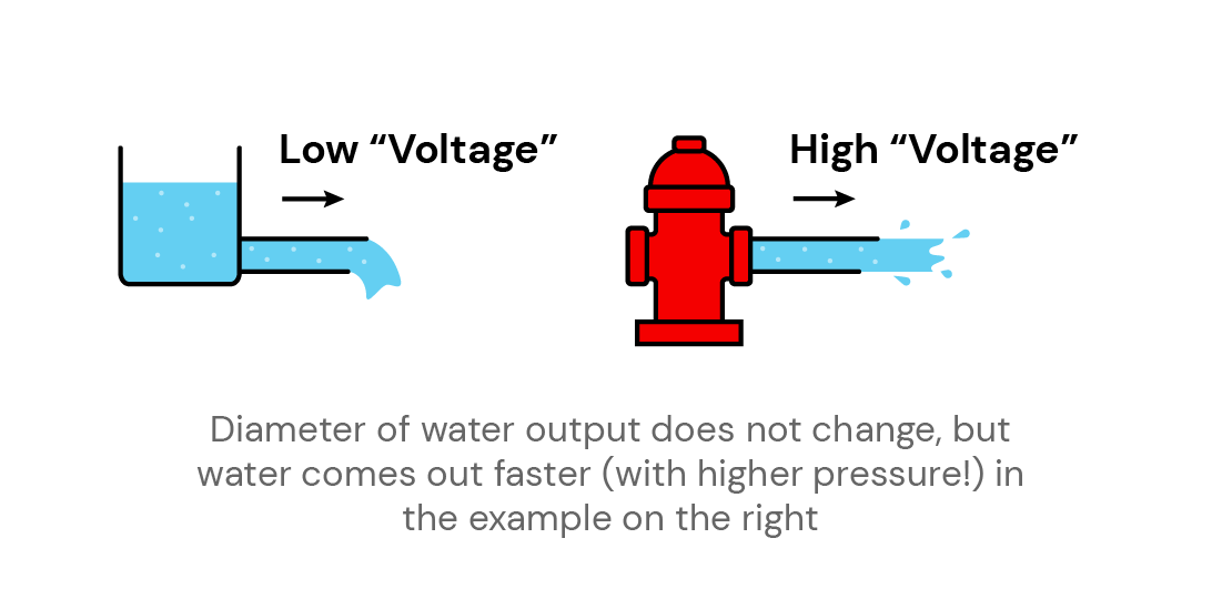
Voltage is the difference in electric potential between two points in a circuit. A higher voltage means there's more energy in the circuit. The units for voltage are Volts (with the symbol V).
Because electricity can be tricky to visualize, let's use a water analogy. Think of voltage as the pressure of water in a pipe. Higher water pressure means that water can flow through the pipe faster. But the size of the pipe stays the same!
Amperage
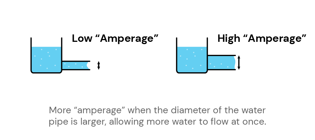
Amperage is the amount of current flowing through a circuit. A higher amperage means there's more electrons flowing through the circuit. The units for amperage are Amperes (shortened as amps, with the symbol A).
Using the same water analogy, think of amperage as the size of the pipe. A larger diameter means that more water can flow through it at once. It's important to note here that you can have a very large diameter pipe with very still water, which is the same as having a high amperage but low voltage.
Understanding these basic units of electricity can help you start building intuition for electric circuits. We won't be going into the math in this guide, but we recommend extra reading, such as this article, if you're interested in learning more about these parameters and their relationships.