LEDs & Blink!
Goals of This Chapter
- Understand how breadboards work
- Obtain a basic understanding of the LED
- Wire up a simple circuit
- Use the Arduino to blink the LED
Building a Simple Circuit!
In this chapter, we're going to put together a simple circuit that demonstrates a small sliver of the Arduino Uno's capabilities. Our circuit will consist of the humble Arduino Uno microprocessor, some wires, a resistor, and a LED (a small but metaphorically powerful light source). Being able to control this LED programmatically is the next step to build your own version of the MIT Illuminations lights at home!
The Breadboard
We've got a lot of components we want to assemble together; how do we actually connect them? Introducing: breadboards! A breadboard is a tool that allows you to easily wire up a circuit by sticking the contacts of components directly into the holes, which we'll call points.
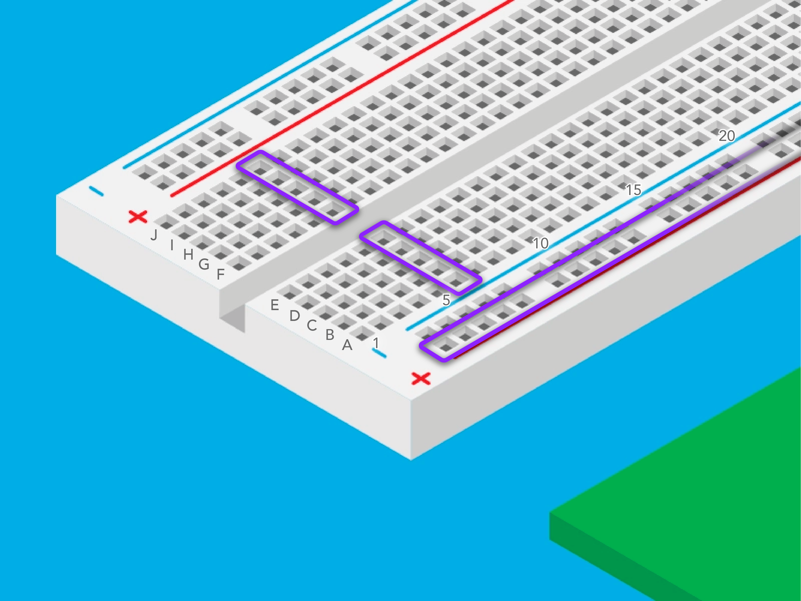
The horizontal rows of five points (i.e.A1, B1,C1, D1 andE1) are connected to each other. There is a middle channel (sometimes called the trough) that separates the two sides (i.e. A1,B1, C1,D1 and E1 are NOT connected to F1,G1, H1,I1 and J1).
The two-hole-wide columns next to both of the long edges of the breadboard are your power rails. Typically, the one next to the red line is connected to your power source (in this case, 5V) and the one next to the black or blue line is connected to your ground (in this case, 0V). The power rails on opposite sides of the breadboard are NOT connected to one another.
In the image below, we're showing three examples of points that are connected to each other - two horizontal rows and one power rail. Note that each purple outline indicates one group of points.
The Light Emitting Diode
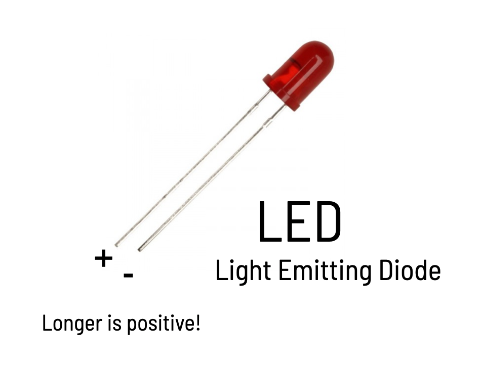
The light emitting diode, or LED, is a component that emits light when an electric current is passed through it, much like a light bulb! However, unlike light bulbs, LEDs are much more efficient (much less of the energy that powers them is converted into heat) and can be used to create a variety of different colors.
The "Diode" part of LED means that it's a component that only allows current to flow in one direction. As such, LEDs have what's called apolarity: there is a positive + side and a negative - side. Like how the battery terminals were labeled in the circuit diagram in Chapter 2.
LEDs have a couple indicators of their polarity. The convention is to have the longer terminal (also called a pin or a lead) and round side be positive +, and the shorter terminal and flat side be negative -. Oftentimes, if you wire it the wrong way around, the LED will not light up when you expect it to.
Let's wire it up!
Prepare the Bus Lines
Our first step is to connect both power rails on the breadboard to each other, and then to a power source. When everything is set up, we call them the power bus lines or buses for short.
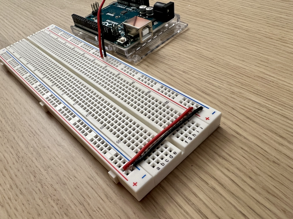
Before there's any electricity involved, we want to connect the power rails on both sides of the breadboard. It's good practice to use red wire for the red power rail (which will be connected to the 5V power supply) and black wire for the blue power rail (which will be connected to ground) - if those colors are available.
On one end of the breadboard, wire the following::
- With red wire, connect the left-side red power rail to the right-side red power rail
- With black wire, connect the left-side blue power rail to the right-side blue power rail
We won't be using both sides of these power rails for this exercise, but it's always a good idea to have them wired up together. It'll save you some prep-work later if or when you do decide to use both sides!
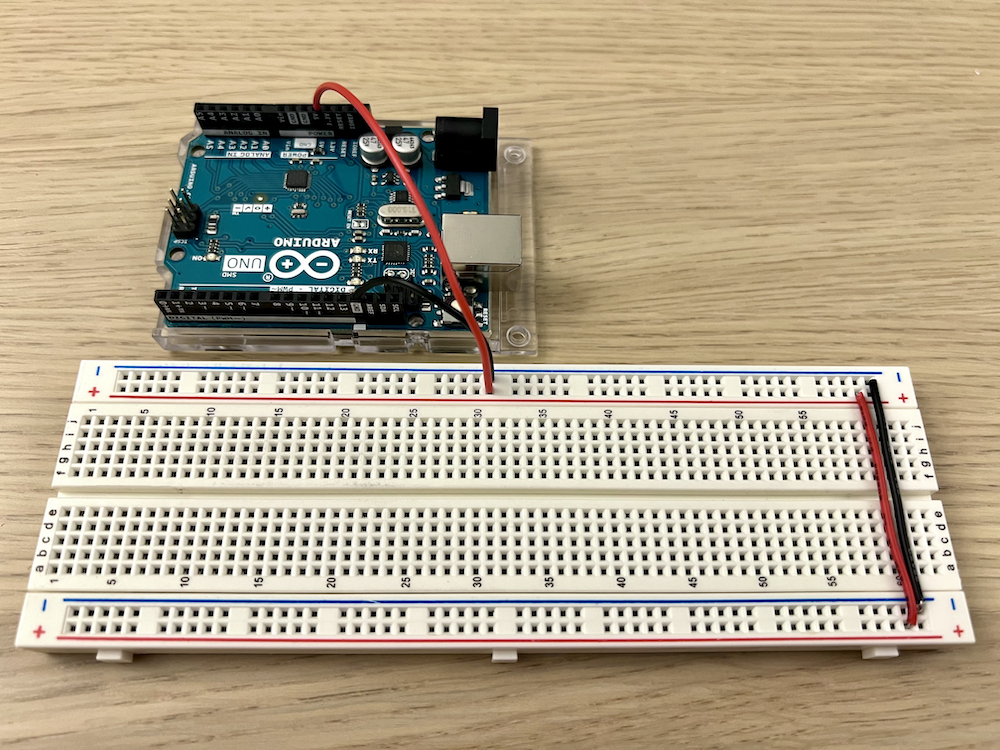
Next, we can connect the Arduino Uno to bring in power to our breadboard. Staying with convention, we will connect the red power rail to the arduino's 5V power supply and the black or blue power rail to the arduino's 0V ground.
On one side of the breadboard, wire the following:
- With red wire, connect the Arduino Uno's 5V pin to a point on the red power rail
- With black wire, connect the Arduino Uno's ground pin (labeled GND; you'll see multiple and they all do the same thing) to a point on the blue power rail
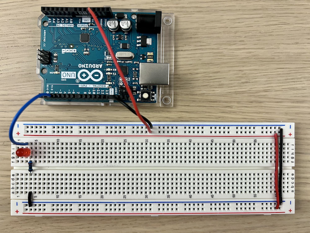
Great! Your breadboard should look something like this:
Attaching the LED
Now that our breadboard has power, we'll add an LED (along with a resistor and a couple more wires). We've provided suggestions of which points to insert wires or the component pins. But as long as you make sure to use connected points on the breadboard, you should be good to go.
Remember that LEDs have polarity, so pay special attention to which terminal goes where! You want the longer pin + to be closer to the 5V power, and the shorter pin - to be closer to ground.
Here's how to set up your breadboard so it looks like the image below:
- Use a wire (any color will do, but it's good practice to use something other than red or black) to connect the Arduino Uno PIN 2 to the board J3
- Grab the red LED. Place the longer pin + intoH3 into H3 and the shorter pin - intoH4.
- Place a 220Ω resistor fromG4 to E4
- Use a black wire to connectA4 to Gnd (the blue power bus that we set up earlier)
Getting the Code Ready to Upload
The final step is to upload code to the Arduino Uno that will tell the LED to blink! This is a step that sometimes can be a bit tricky (connection errors, etc.) so take your time with it and believe in yourself!
Arduino calls these code files "sketches,"and they provide some great instructions here!
Uploading the Code!
Now, copy and paste the code below into your Arduino IDE and hit upload! If you've done everything successfully, you should see your LED blinking! Hooray!
Take a look at the code and see if you understand what each line does. Try modifying a couple of elements and then reuploading to see how the LED responds. Can you make it blink faster?
Troubleshooting
If something doesn't work - no fret! It's all part of the learning process.
Review the steps carefully, making sure you've wired up everything as intended. Even a single connection being broken may cause your circuit to not work!
If you're getting errors in the Arduino IDE, try to read through the error messages. They're more helpful than people often give them credit for. There may be a lot of jargon, but usually a line or two will be in human-readable language that will help you resolve the issue!
