WS2812b LEDs
Goals of This Chapter
- Obtain a basic understanding of individually addressable LED strips
- Use the Arduino to light up the WS2812b LED strip
What are WS2812b LED strips?
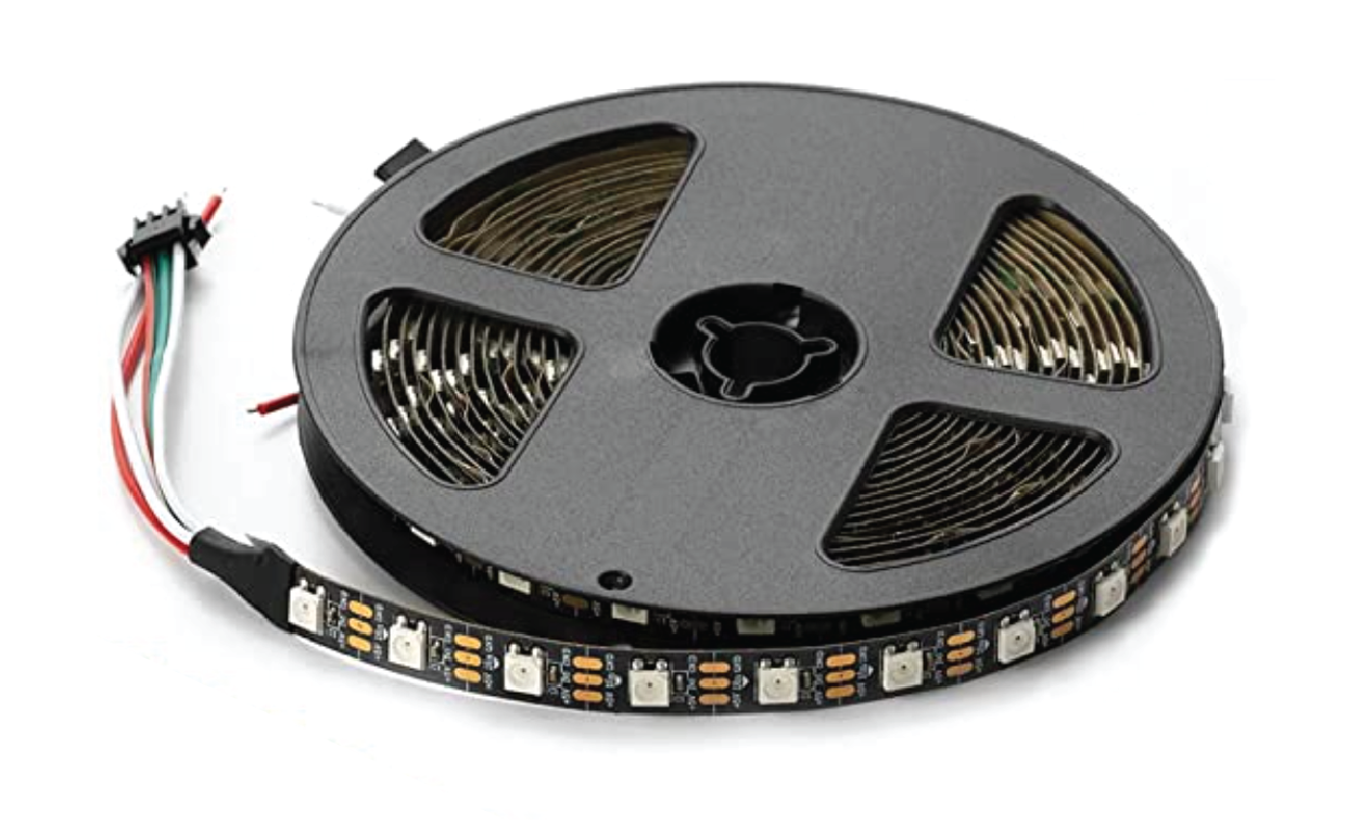
In order to make MIT Illuminations-style lights at home, we need to scale up from programmatically controlling one LED to a lot at once! WS2812b LED strips are very popular among the maker community because of their versatility and ease-of-use.
These LEDs are very popular among the maker community, and because of their versatility and ease-of-use, a lot of similar flavors can be found in art/lighting-related installations.
There are three primary properties that make the LEDs in WS2812b strips stand out over other options: RGB, 5V, and individually addressable.
RGB LEDs
WS2812b strips contain RGB LEDs, meaning each LED is actually a combination of three even tinier LEDs - one that is Red, one that is Green, and one that is Blue (hence the RGB). These are great because each color can be turned on to a different brightness level (i.e. red at full bright, green at half bright, and blue off) in order to produce millions of different colors.
There are lots of other kinds of LEDs, like RGBW LEDs, which include a white channel. This white channel can help the LED emit a more pure white color, or give the LED a bit more brightness in general.
5V LEDs
The 5V LEDs in the WS2812b strips work well with the Arduino Uno we're using for our projects. By default, the output of an Arduino's digital pins is 5V, which means we can directly plug in the data line of our LED strip (to be explained later).
The most common type of LED takes 12V power, but there are plenty of others too. While the 12V tends to be more durable and brighter, they require additional components to be able to work with our Arduinos.
Individually Addressable
The WS2812b strip has three connections, also known as pins: Power5V, Data In Din, and Ground 0V. With these three pins connected to an Arduino, you're able to set the brightness and color on each individual LED in the strand! This is why we say it's “individually addressable” - you can control each LED independently.
This is because the Arduino sends more than just an 'on' or an 'off' signal to the LED strip. Instead, the Arduino uses a protocol (WS2812b) to communicate to a chip inside the first LED, which in turn communicates to the next LED down in the line, and so on.
The WS2812b Data Sheet
Most electrical components come with an important document that describes their properties, operating characteristics, and other important details. This is usually called a data sheet! The WS2812b's data sheet probably contains more information than you need right now, but it's good to have it around for reference.
Connecting the WS2812b LED Strip
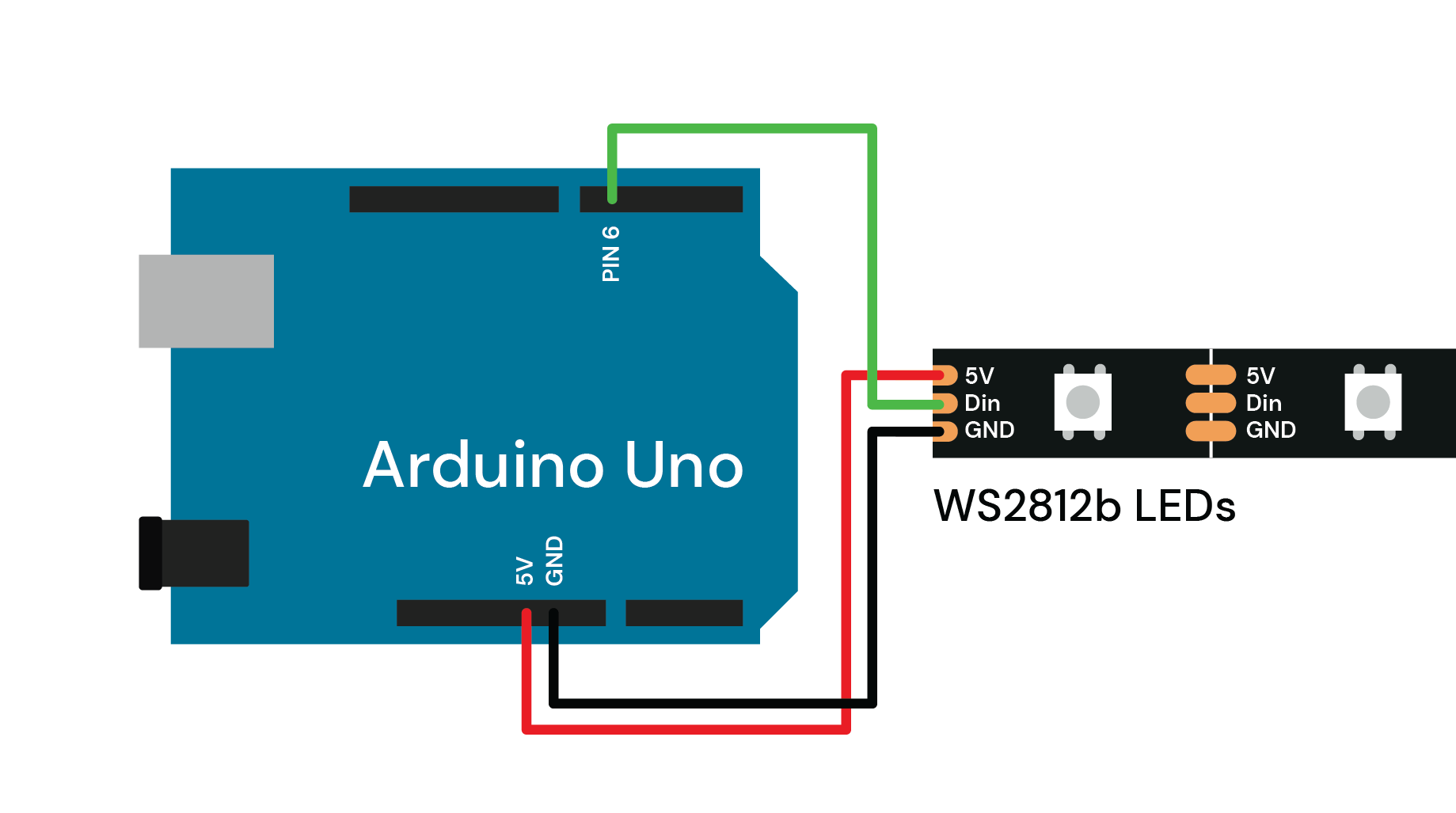
Now that we know what we're working with, it's time to connect the LED strip to your Arduino! Take a look at this diagram to see how we're going to connect everything:
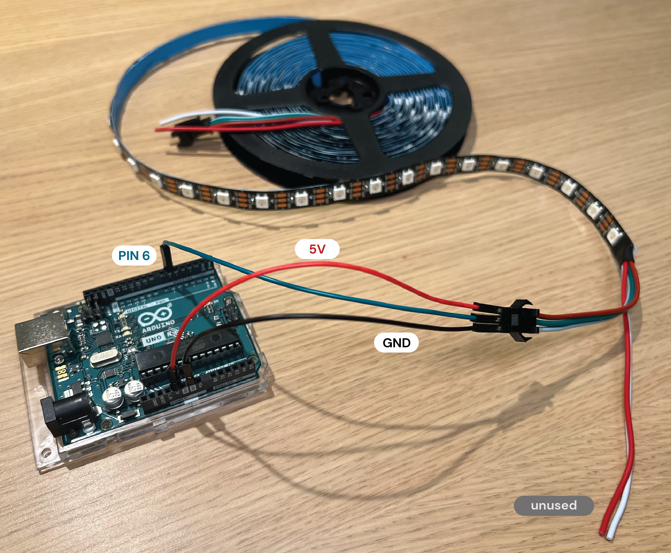
We'll have to make 3 connections between the Arduino Uno pins and the copper pads at the end of the LED strip. A quick and easy way to do this is to put one end of a wire directly into the '3pin JST-SM' connectors on the copper pads, and the other end directly into the Arduino pin. Like we mentioned in Chapter 4 when we wired up a breadboard, it's good practice to use red wire for the 5V power supply and black wire for the 0V ground (labeled GND) - if those colors are available.
You'll also notice that there are these copper pads after every LED on the strip, so you can cut it to whatever length you want! You could also extend it by soldering multiple strands together, but there is a limit to how many LEDs you can power and control at once - so just keep an eye out if things start misbehaving.
Other wiring diagrams online for similar LEDs might have you put a resistor in between PIN 4 of the Arduino and the Din of the LED strip, instead of a direct wire like we show here. This added resistor is meant to help mitigate noise and bad signals, but it's usually not necessary for shorter strands like the one we recommend for this project. You may need one if you choose to extend your strip though!
Lastly, just like how the polarity of a single LED matters, the polarity/direction does matter on these LED strips too. The WS2812b LED strip only has a Data In (Din) pin to keep things simple, but other strips may come with an arrow that indicates the direction of data flow. If that's the case, you should make sure you distinguish between Data In (Di or Din) and Data Out (Do or Dout) on your strip.
Upload a Program!
To communicate with our newly wired LED lights, we're going to use a library called FastLED. Libraries (like this one) take a lot of the hassle out of writing code for a specific component from scratch. Better yet, they usually come with a lot of examples that you can use as a starting point for your own projects.
One way to add a library is to install it using Arduino's built-in Library Manager. Open Arduino IDE and then go to Sketch > Include Library > Manage Libraries. Search for FastLED and then click Install.
Next, let's open up an example sketch (which is what Arduino calls code files) and try making our lights change colors. Go to File > Examples > FastLED > Cylon
When you open up the code, take a quick read through it. You'll notice there are 2 variables that are relevant to us:
NUM_LEDSis the number of LEDs in your strip - you may have more than what we're able to power with our 5V Arduino output. Set that to a low number like 24.DATA_PINis whatever pin you've connected the Din of the LED strip to on the Arduino. It's initially set to 2, but you'll want to change it to 4 (since we're using pin 4 on the Arduino).- Note that you can leave
CLOCK_PINuntouched, since we're not using it.
The code you end up with should look something like this:
When you hit upload (you may have to make sure the port and settings are correct!) your LED strips should start to light up in a cool pattern! Give yourself a pat on the back if you made it this far. You deserve it!
After you have your LEDs working, you can play around with different parameters and take a closer look at the code. There's a great tutorial on Instructables which explains the world of the FastLED library, which you can find here.
Troubleshooting
If something doesn't work like how it's supposed to, start by seeing if there are any errors in the Arduino IDE console output. Make sure you have the board and the port selected correctly - if you don't remember how to do this, check out Arduino's Guide.
If everything is uploading correctly, but you're not seeing the LED lights change colors, double check and make sure your wiring is correct. Make sure the code is copy pasted correctly from above, and that the variables are set correctly.


